
DCS-BIOS Board ‘eco-system’
most basic requirement
A single Arduino board will suffice for a DCS-BIOS installation, an arduino board, communicating to DCS via USB connectivity, is more than suitable to do this, however it lacks any scalability as you add more pins…
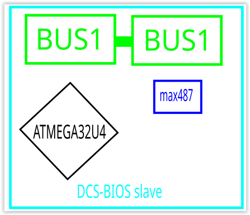
the solution to this is a or a single (purpose built) DCS-BIOS slave board, also communicating to DCS via USB connectivity.
then the next step…
setting up for a modular / scalable framework
In order to make your DCS-BIOS framework scalable you will need to add
1x single (purpose built) DCS-BIOS Master board
Note: only the one master board is required for the entire framework
+ at least 1x (purpose built) DCS-BIOS slave board (if you’re moving to a scalable solution, its more than likely though that you have already filled all the available output pins on a single card & now need a second slave board.
Note: the master board can only provide the communication framework for the slave cards, it cannot provide ANY output pins to panels.
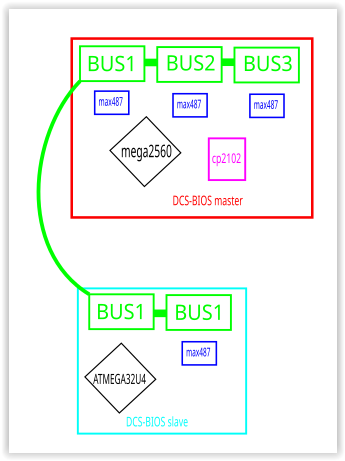
you could also start out with a single master & slave board, if you know you will be expanding short term, realistically it’s not required until you need a second slave card.
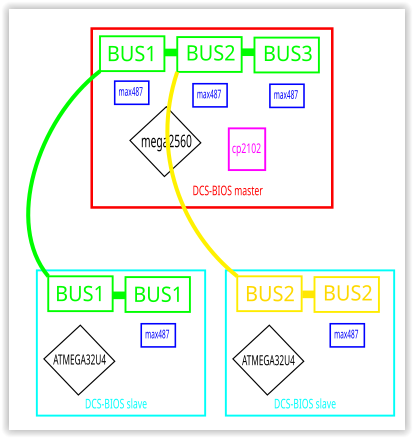
If you’re intending to, or currently building a full simpit or multiple consoles, optimally you will require at least one slave board per console.
the pink board illustrated above is a special high capacity slave board that utilises a mega2560 (instead of a mega328) microcontroller, to allow for more pins available to a single board, this would be useful for panels that are highly saturated with required output pins, (such as a warning panel, with lots of individually lit LEDs) this board is not essential but available as an option.
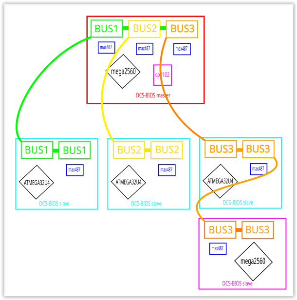
next step is populating panels to each board & adding extra slaves to each BUS to accommodate required pin outputs to each panel.
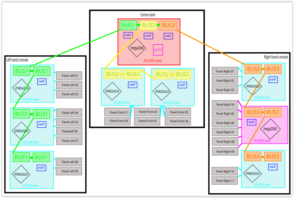
The example above is probably a massive overkill for any DCS-BIOS requirement, this is simply to illustrate the scability, the actual maximum of slave boards is 128 boards….per BUS! (depending on signal integrity).
Far more than than would ever be required by your average DCS aircraft module.
More than likely you will be able to get away with a single DCS-BIOS slave board for each console for all but the most complex of aircraft.
Please refer to the AH64D example below.
12 Volt DC power distribution
This DCS-BIOS board framework can also provide 12Volt DC throughout the pit, with a reasonable amount of current (< 2 Amps per BUS), suffice to run just about anything you could dream of within the pit;
- LED lights & lamps of all kinds
- LED, OLED & LCD displays
- Servos
- electro-magnets
Note: The exception being high-powered devices, such as butt-kickers, large audio amplifiers etc.
Freejoy Boards
Building a electronically modular simpit
all of the switches/buttons are connected to the Freejoy boards for input back to DCS as the sim, where as the outputs (LED’s etc) are connected to the DCS-BIOS board framework.
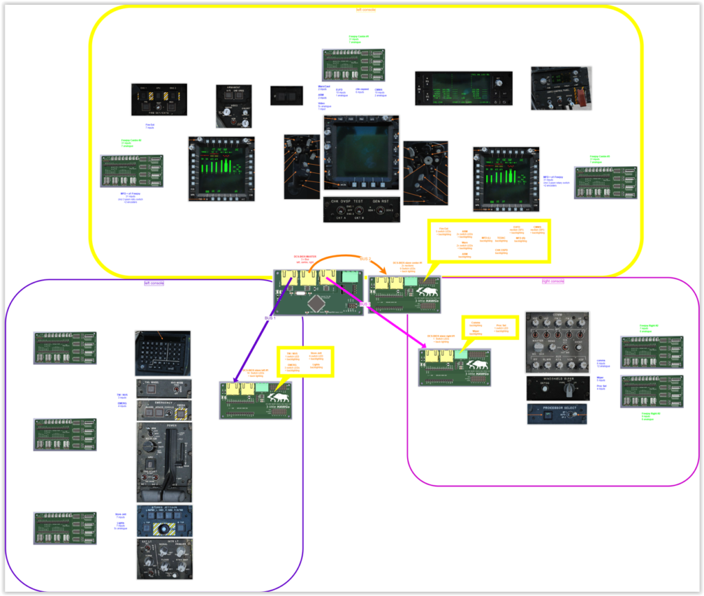
There will be a variance in the number of each type of board required:
there will be far more inputs (switches/buttons) going to available freejoy board pins, than there will be DCS-BIOS board available pins going to panel LEDs.
FreeJoy boards illustrated on the outboard of the panels
DCS-BIOS boards illustrated on the inboard of the panels
So as can be seen above there may be 2 or 3 Freejoy boards required per console, but only a singular DCS-BIOS board required (illustrated above on the inboard of the panels), depending on the number of LEDs or displays needing output.
Note: each individual Freejoy board is connected via a USB connection, these boards cannot be joined together.
Seperation of roles (Freejoy vs DCS-BIOS)
FreeJoy boards (on the left of the illustration) handle all the inputs (button/switch presses)
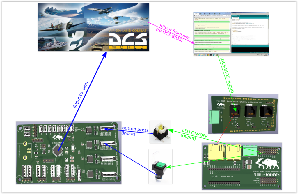
Whereas DCS-BIOS boards (on the right) handle all the output (LED flashing/turning off/on etc).
Note: whilst every button/switch will require an input connection to a freejoy board, not every button/switch will require any DCS-BIOS connection (no LED back lighting or integration), therefore freejoy board connections will significantly outnumber DCS-BIOS board connections